3D art by Nathan Young
Article by Joe Wilson
The Bevel Effect
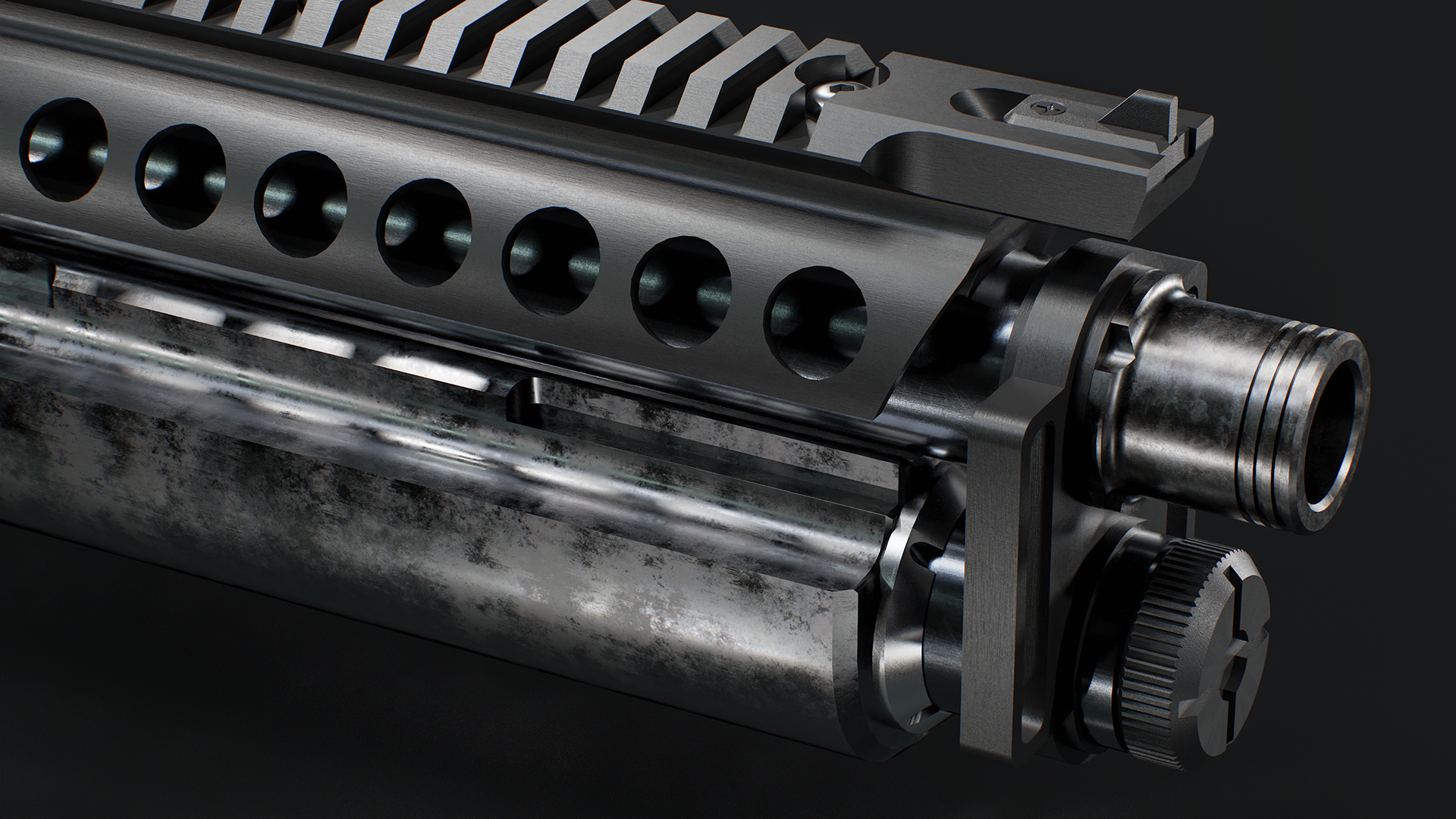
Meticulously modeling beveled or rounded edges on your 3D mesh has long been an exhausting and mind-numbing process. Countless hours can be saved by generating the same level of detail in your 3D material using Marmoset Toolbag’s Bevel shader!
By procedurally generating beveled detail in your material, you can eliminate the time-consuming process of adding edge loops for subdivision control, streamlining your entire modeling workflow. The Bevel shader simplifies your base mesh, providing an iteration-friendly process that allows you to focus more on design and less on the technical aspects of modeling and topology.
The Bevel Effect
Meticulously modeling beveled or rounded edges on your 3D mesh has long been an exhausting and mind-numbing process. Countless hours can be saved by generating the same level of detail in your 3D material using Marmoset Toolbag’s Bevel shader!
By procedurally generating beveled detail in your material, you can eliminate the time-consuming process of adding edge loops for subdivision control, streamlining your entire modeling workflow. The Bevel shader simplifies your base mesh, providing an iteration-friendly process that allows you to focus more on design and less on the technical aspects of modeling and topology.
Bevel Basics
What is Bevel Shading?
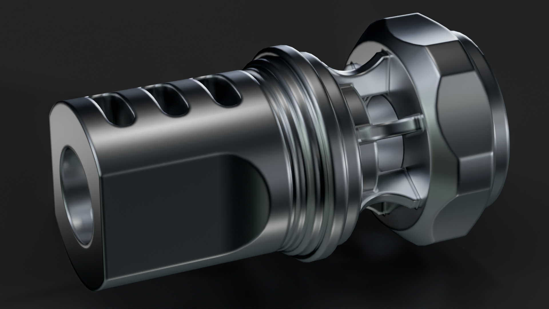
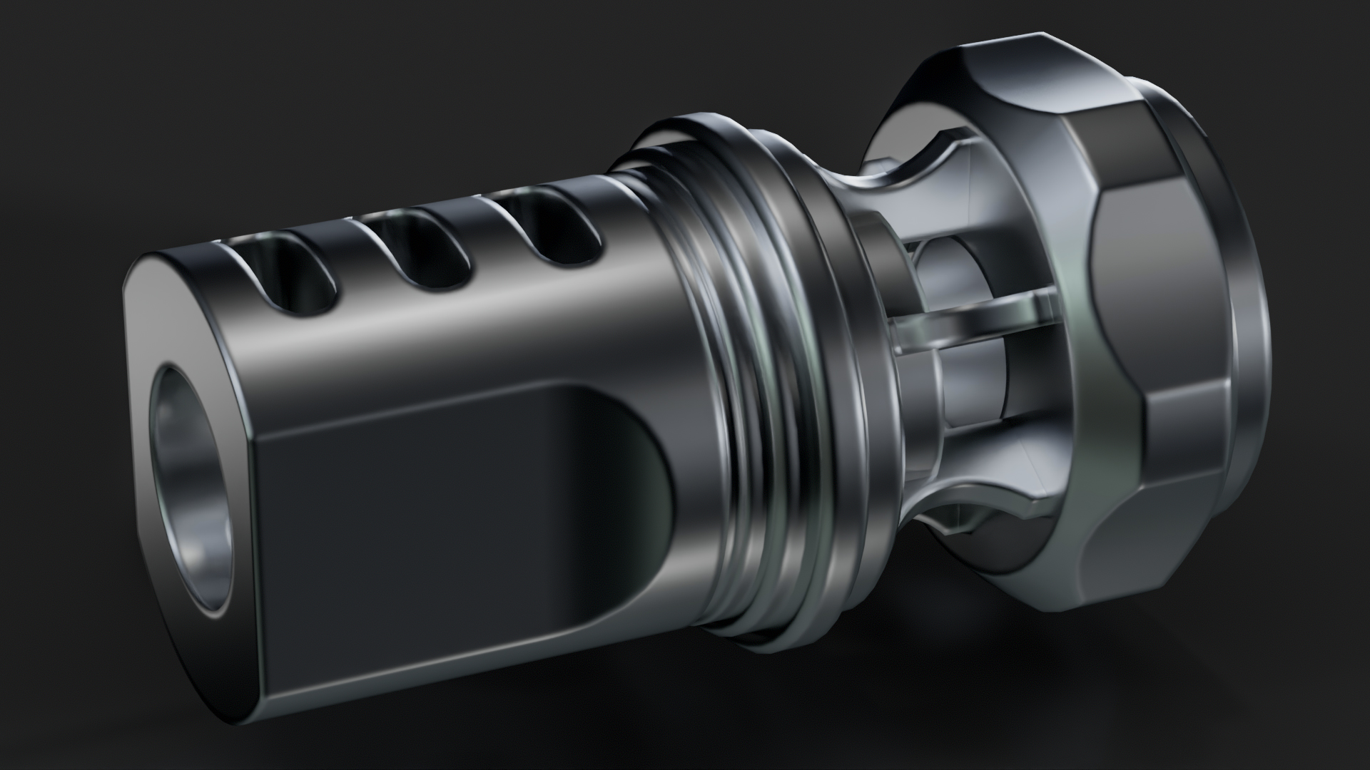
Bevel shading is a technique similar to normal mapping that alters normal directions along hard edges to create the appearance of a rounded edge. The edges of real-world objects tend to be chamfered or rounded over. Bevel shading is a quick way to add realism and believability to your models by mimicking this effect.

The bevel shader creates a ray-traced lighting effect that mimics rounded edges. However, it does not alter the geometry or shape of the mesh. This means it’s best suited for small to medium-sized details and edges that would normally be represented in the normal map. Larger forms that affect the object’s silhouette should be modeled into the base mesh.
How to Apply the Bevel Shader
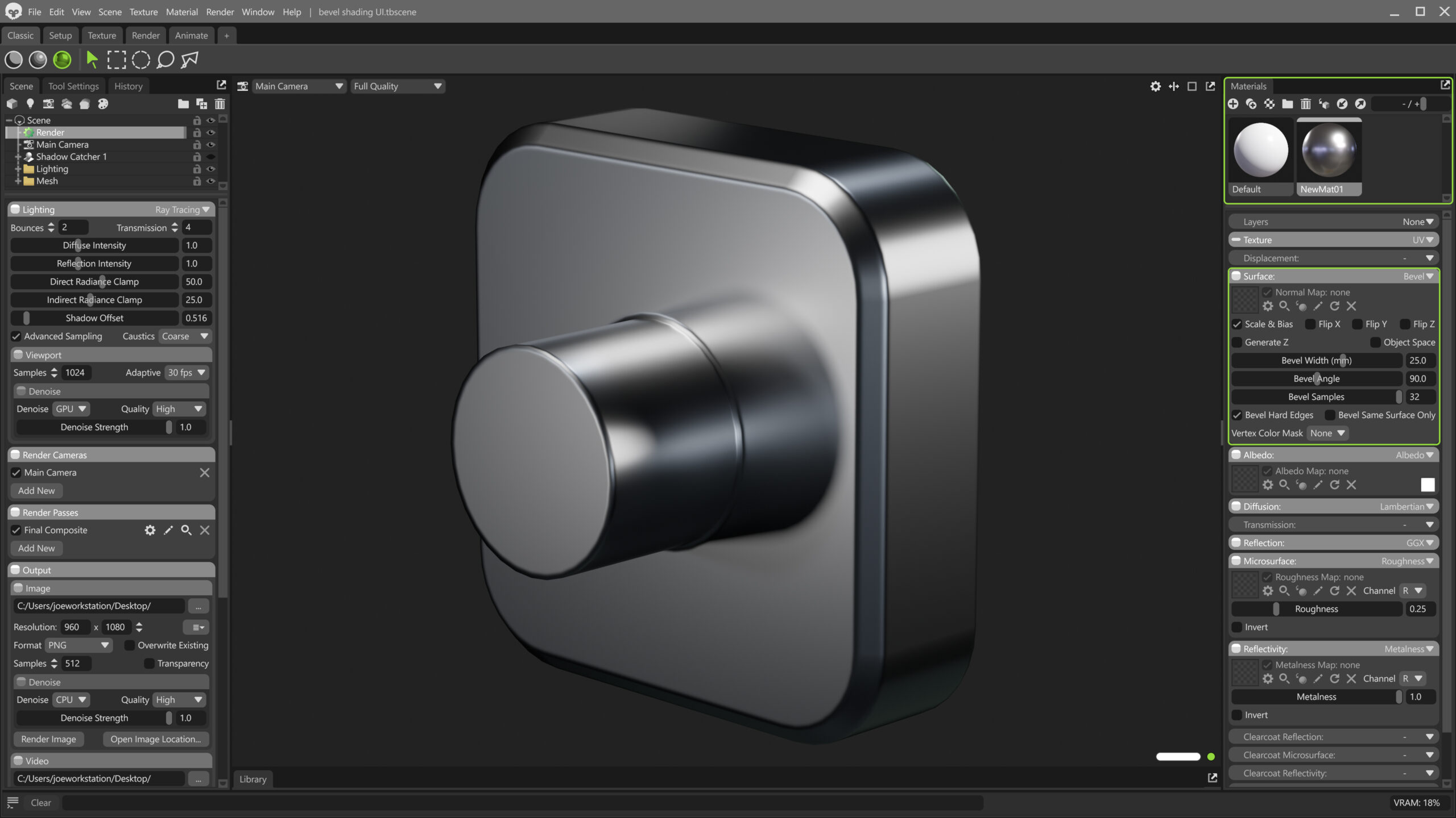
Bevels are controlled by the material applied to your mesh object. Bevel shading in Toolbag can be enabled in the Materials window by selecting Bevel in the Surface module.
Note: The bevel shader is not supported in the Raster renderer. Make sure Hybrid or Ray Tracing is selected to preview the effect. Bevels can be baked to textures to view the result in Raster mode as well.
Controlling the Bevel Effect
The material settings provide a number of options for configuring the style and look of the bevels.
Bevel Width
Controls the size of the bevels. The value is set in millimeters. If the setting you’ve configured does not seem right in relation to the size of your object, make sure the scene units are configured correctly in the Scene object.
Bevel Angle
Determines how high the angle difference between two faces needs to be before a bevel will automatically be drawn at the edge. If you’re using hard edges to control bevel application, you can generally set this to a high value or ignore it.
Bevel Samples
Sets how many ray-tracing samples are used to calculate the bevel shape. Larger bevels typically require a higher sample count to look good. Fewer samples will result in a higher frame rate, so consider using a lower value when previewing, and a higher value for your final renders.
Bevel Hard Edges
Determines whether the smoothing groups or hard edges set in your 3D application control the placement of the bevels. This option gives you more control over where the bevels appear and is recommended for complex objects.

Bevel Same Surface Only
Controls the behavior of bevels when mesh objects intersect. When enabled, intersecting objects will ignore each other. When disabled, a bevel will be generated at the intersection point. This is a great way to mimic complex molded or welded parts.
Varying Bevel Size
Complex assets often require multiple objects made from different materials. For example, a weapon or vehicle may have metal, plastic, and rubber parts, each requiring a different bevel size.
Unique Materials
The most convenient way to control bevel size is by applying a unique material to each part. This makes it easy to create larger bevels for soft rubber and plastic parts, and finer bevels for metal. Applying unique materials to different surface regions is necessary for Material ID maps as well, so this process serves double duty in baking workflows.

You can apply unique materials to sub-sections of objects or polygon regions for finer control. This is especially handy if you need smaller bevels for detailed parts on a complex, contiguous mesh. You can’t apply materials to polygon groups directly in Toolbag, so you’ll need to select the polygons and apply a unique material in your 3D application before you export the mesh file.
Vertex Color Masking
If you need more control, you can select a Vertex Color Mask channel to vary the size of bevels within a single material. Vertex masking uses the color value as a multiplier on the Bevel Width setting. For example, if Bevel Width is set to 5mm, a vertex color value of 0.5 would create a size of 2.5mm for that region. You can think of the Bevel Width setting as the maximum size in this case, with vertex colors being used to reduce the size where necessary.
Note: Toolbag does not currently support vertex color painting, so vertex color data must be authored in your 3D application.

Material Layering
Material layering can be configured if even more control over bevel size is required. With this workflow, you can add multiple layers, each with dedicated size values. Masking can be controlled with images (UVs are required in this case) or vertex colors.
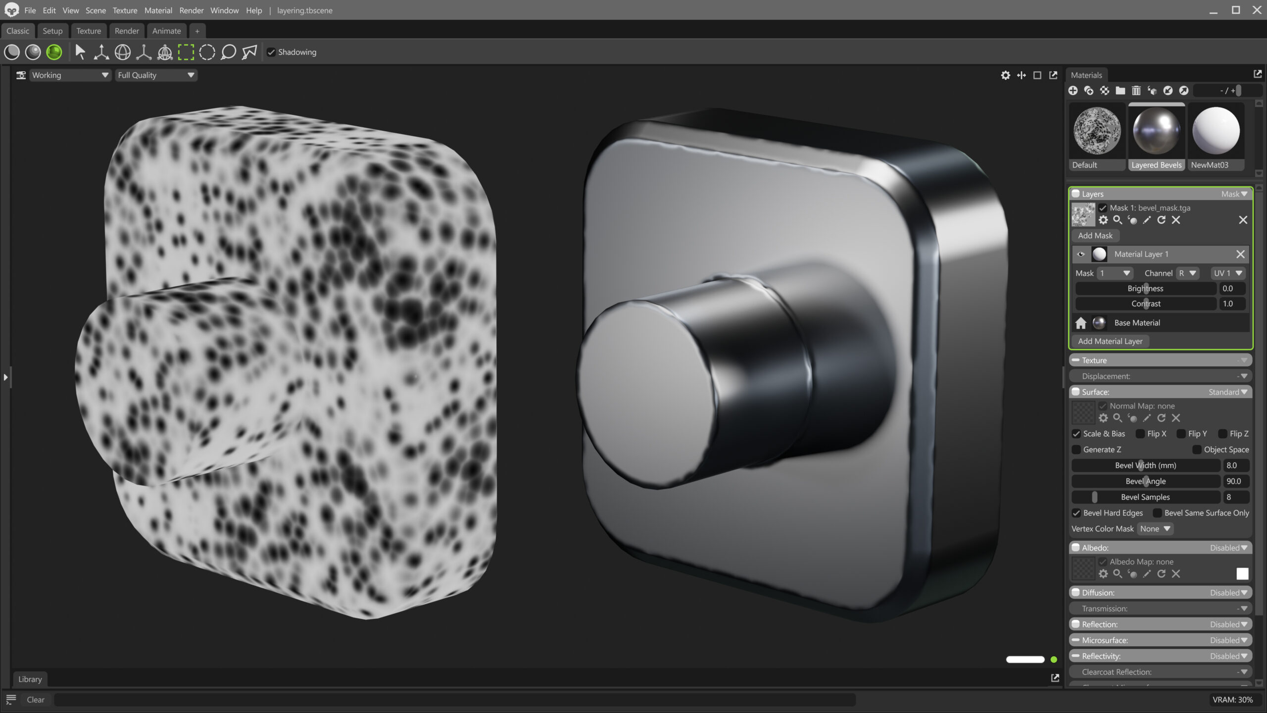
In the example above, a procedural noise texture was created with a Texture Project and used as a mask to blend between two material layers. Each layer has a different Bevel Width, resulting in a dented edge effect.
Learn about Material Layering in our video tutorial
Bevel Rendering
As noted previously, bevel shading is a ray-traced effect, so ensure you have Hybrid or Ray Tracing rendering mode enabled in the Render object for viewport preview and final renders.
Bevel Real-Time Preview
Previewing bevels as you create your mesh can be tricky. While some modeling applications have a similar bevel or rounded edge shader, most do not have an easy way to display a real-time preview.
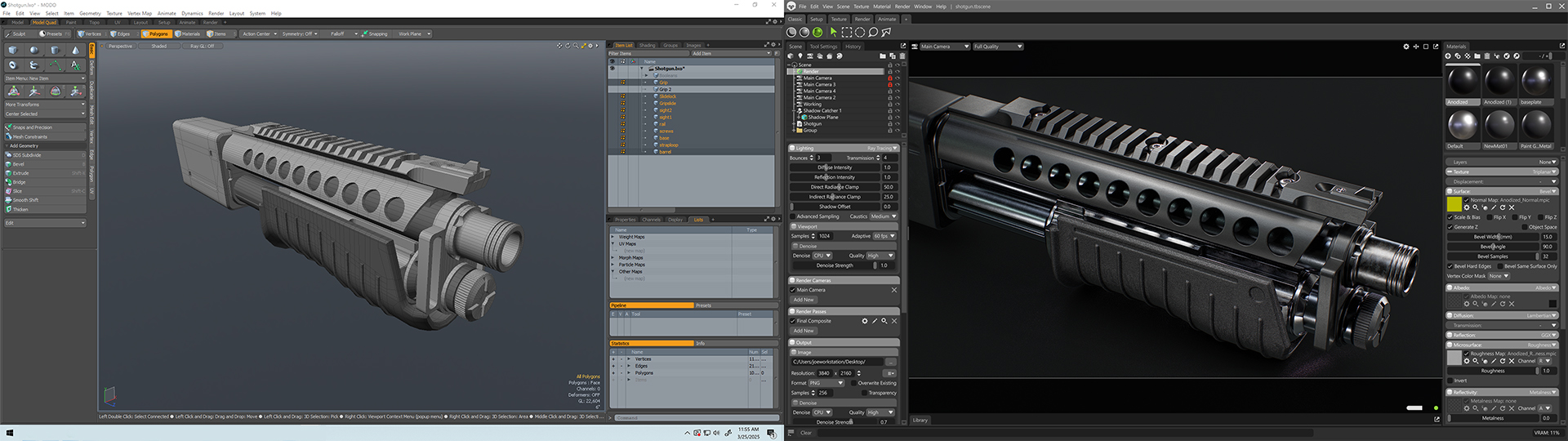
I keep my 3D modeling application open on one monitor, with Toolbag on a secondary screen. This streamlines the preview process. I re-export my mesh whenever I want to see an update, and then switch to Toolbag, which will automatically reload the mesh. This gives me an easy way to see a faithful representation of the final bevel effect.
Bevel Shadows
As mentioned, the bevel shader does not modify or displace the actual geometry. Shadows are cast from the raw mesh geometry, which means harsh shadows can appear where you might expect the light to wrap around beveled edges.
Shadow faceting can appear with coarse low poly meshes as well. You may notice these undesirable rendering artifacts if you’re using a duplicate of the low poly to generate bevels for your bakes.
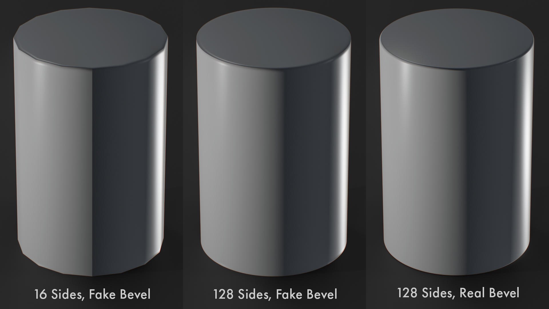
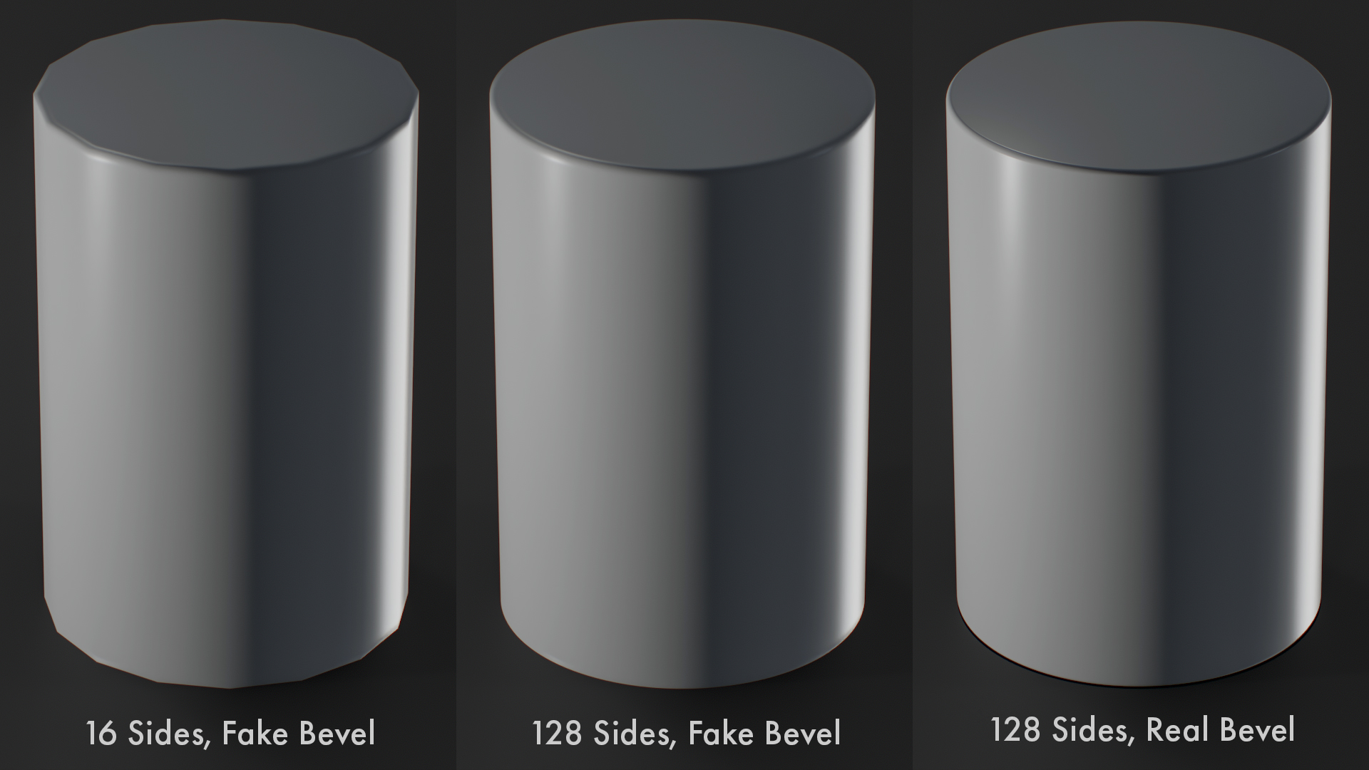
To improve shadow faceting artifacts, adjust the Shadow Offset value in the Render settings. Note how adjusting this setting improves the bevel transition at the top as well as the faceting we see in the midsection with the 16-sided cylinder.
Bevel Width vs Polygon Size
Bevel shading can create artifacts if the bevel size is set to a value larger than the polygons that make up the mesh. The shader attempts to draw overlapping bevels, which can cause faceting to appear.

This can be especially problematic with thin or narrow parts. Try to stick to sizes that make physical sense; in other words, avoid adding a bevel that is thicker than the individual elements that make up a part.
For complex parts, you can adjust the bevel size for different areas by making use of the techniques covered in the Varying Bevel Size section.
Bevel Baking
Bevels and baking are a natural fit. As mentioned above, bevel shading is similar to normal mapping, which means it’s compatible with industry standard baking workflows for game engines and real-time renderers.
To get started, add a Bake Project to your scene and load the corresponding meshes into the High and Low slots. You can speed this process up by using the Quick Loader.
Learn more about Bake Projects
Map Types
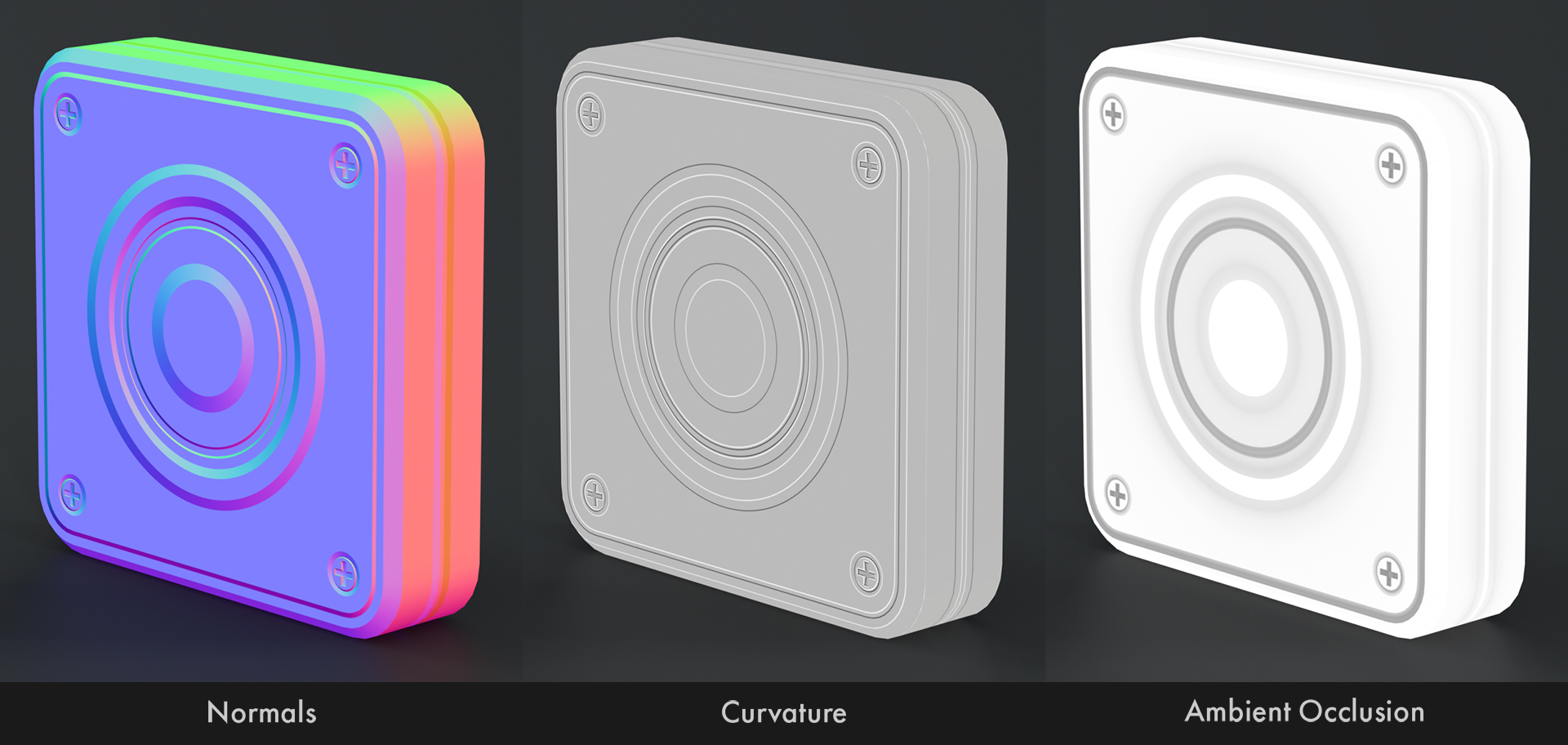
Bevels create normal map detail and affect the Ambient Occlusion and Curvature maps, so you don’t need to use another application to generate this data. This feature is exclusive to Toolbag’s baker and makes it easy to jump straight to the texturing process.

Mesh Considerations
Toolbag does not currently support baking texture maps directly from the low poly model, so you will need a high and low polygon pair. You may be able to use a copy of your low poly mesh, with a bevel material applied, as the high poly. For simple assets, this can work well.

While using the same mesh for both the high and low slots can be an easy way to speed up the modeling process, there are situations where the meshes should be different. Let’s dive into the details.
Varying Levels of Detail
As with traditional baking workflows, there’s often a need for different levels of detail in the high and low. This could be fine surface details like screws, panels, seams, or other types of greebling that only exist in the high.

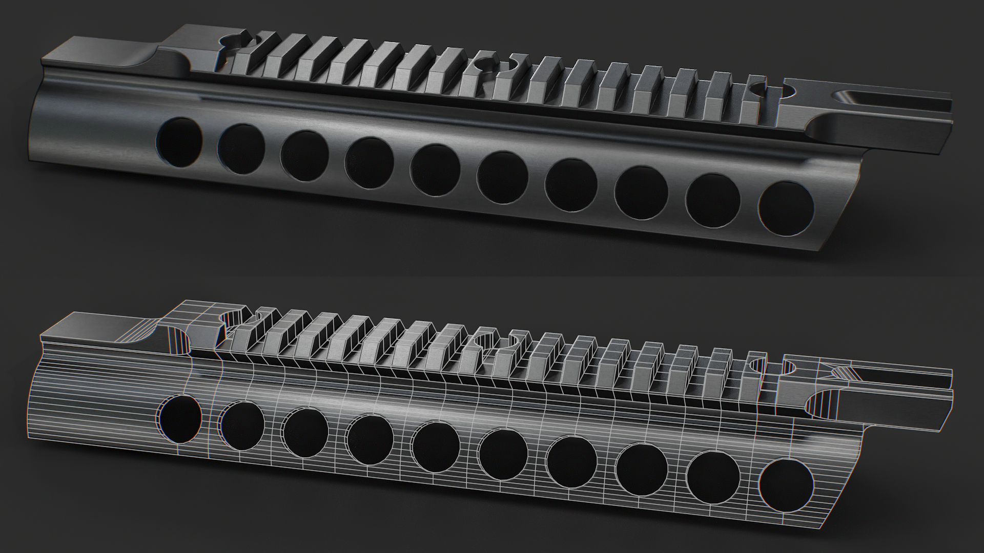
With this example, the high poly mesh is very different from the low, as it often is with traditional baking workflows. Rather than being a replacement for needing to create a high poly mesh, the bevel shader workflow provides an alternative to creating a detailed subdivision surface mesh. We can work with a lighter, easier-to-edit mesh and worry less about quad-based topology, edge flow, control loops, etc.
There are cases where you may want details in your low that aren’t in your high as well. That may sound counterintuitive, but if we consider that the high poly is not the end goal but rather a means to generate the normal map, it makes more sense. In this case, I want to keep the high poly simple so it’s easy to edit during the initial creation process. However, this might be a part that will be seen up close, so for the final low poly mesh, I added a chamfer to the metal shell and rounded the edge for the soft plastic part to improve the silhouette and shading.

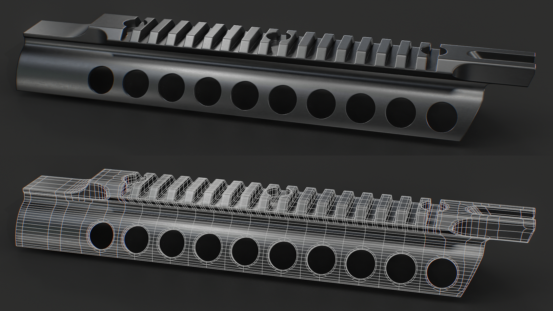
It’s worth mentioning that the wireframes are rather messy in some of these examples. While you want to make sure the final topology for the low poly mesh is clean, efficient, and shades well, this doesn’t necessarily apply to the high poly. As long as the high shades well and the bevels work as expected, there isn’t any need to clean up the mesh or follow the traditional rules that you might be familiar with for subdivision modeling. This allows us to work more freely, using techniques like booleans or CAD modeling that would otherwise be considered unsuitable for this kind of work.
However, you may need to triangulate complex n-gons before importing your mesh to Toolbag. In these examples, I have broken the n-gons up minimally for the wireframe renders to illustrate how messy the geometry is. But for the final bake, the meshes have been triangulated to ensure the shading is correct and that complex n-gons do not collapse into unexpected shapes.
Seams and Hard Edges
As with traditional baking workflows, we need to be mindful of how our UVs and hard edges are laid out for the low poly mesh. If a hard edge is used in an area where the UVs are a contiguous island, this will create a seam artifact in the normal map.

To counteract this, it’s important to make sure our UV islands are split wherever we use hard edges. With a bevel baking workflow, we will typically control the bevel placement with hard edges. This means that if our high and low poly meshes have the same geometry and mesh normals, we may need to use too many hard edges and split our UV layout into more islands than is necessary for the low.
The image below shows that the key difference between the high and low models is how the hard edges or mesh normals are set up. For the high, the hard edges define bevel placement. For the low, the normals are averaged so we can use an optimal UV layout. Face-weighted normals would be appropriate for the low as well.

Merging Meshes
While it isn’t necessary to merge the parts that make up the high poly mesh, it can be beneficial to do this for the low poly. Parts with large intersections or overlaps can create inefficient UV layouts, as you end up dedicating texture space to areas that won’t be visible. Note the black areas in the image below.

Merging is a good way to squeeze out the maximum amount of detail for your textures. Especially with complex assets, as the empty sections can be filled with smaller parts. That said, merging can increase the triangle count and add time and effort to the process. So it’s worth considering how beneficial it is on a per-asset basis.
Material IDs
Using unique materials for different surface types is a great way to define the regions for Material ID maps and gives you control over the bevel settings for those regions. If possible, we recommend setting up your scenes this way.

As covered in the Varying Bevel Size section, assigning more materials can be a good way to fine-tune the bevel size on complex parts. However, this can mean using more materials than necessary to define the surface regions, resulting in too many colors in the Material ID map.

As a workaround, you can define your ID colors manually. This can be accomplished by configuring the albedo color for each material, allowing you to use the same color for different materials that share the same surface type.
For example, if you have three materials to set different sizes for bare metal parts, make sure the albedo color matches for all three. Then, in your Bake Project settings, hit the Configure button in the Maps panel, and enable the Albedo map type.
Modeling Workflow
Whether you’re baking or creating meshes meant to be used directly for rendering, there are a few topics to consider while modeling.
Bevels vs Subdivision Surfaces
Bevel shading is an efficient method to add rounded edges to complex hard surface objects. Let’s see how the bevel workflow compares to traditional sub-d modeling techniques.
Bevel Workflow
Pros
- The base mesh is typically simpler and easier to edit.
- It’s faster to build the low poly mesh from the base mesh. Sometimes, they can use the same geometry.
- The bevel edge width can be adjusted at any time.
- Intersecting meshes create a bevel line, mimicking welded parts without needing to boolean or merge parts.
- Boolean subtraction techniques can be used with relatively minimal cleanup.
- Bevel shading works better with geometry from CAD modeling programs.
Cons
- Curved or rounded surfaces may require more geometry in the base mesh, as the mesh won’t be subdivided and smoothed.
- It’s not possible to create different bevel profiles or shapes, ie, roundovers vs chamfers.
- Managing different bevel sizes on a complex, contiguous mesh can be complicated.
- Previewing bevels requires using a renderer that supports the effect.
- Topology meant for the bevel workflow generally won’t work well for sculpting.
Subdivision Workflow
Pros
- Great for curved and organic shapes.
- Curved surfaces can sometimes be created with a simpler cage mesh.
- Provides finer control over the exact size and profile of bevels.
- The level of detail can be adjusted dynamically.
- Meshes prepared for subdivision are more suitable for sculpting.
Cons
- Adding bevels or hard edges requires a complex network of control edges that can be difficult to maintain if the design changes.
- Requires clean flow and typically quad-based mesh construction.
- Working with booleans and CAD data can be challenging.
- Subdividing creates a dense mesh, often millions of triangles for complex assets.
- When subdivided, the shape of the cage mesh can change considerably, making retopology more difficult and time-consuming.
Bevel Workflow
Pros
- The base mesh is typically simpler and easier to edit.
- It’s faster to build the low poly mesh from the base mesh. Sometimes, they can use the same geometry.
- The bevel edge width can be adjusted at any time.
- Intersecting meshes create a bevel line, mimicking welded parts without needing to boolean or merge parts.
- Boolean subtraction techniques can be used with relatively minimal cleanup.
- Bevel shading works better with geometry from CAD modeling programs.
Subdivision Workflow
Pros
- Great for curved and organic shapes.
- Curved surfaces can sometimes be created with a simpler cage mesh.
- Provides finer control over the exact size and profile of bevels.
- The level of detail can be adjusted dynamically.
- Meshes prepared for subdivision are more suitable for sculpting.
Cons
- Curved or rounded surfaces may require more geometry in the base mesh, as the mesh won’t be subdivided and smoothed.
- It’s not possible to create different bevel profiles or shapes, ie, roundovers vs chamfers.
- Managing different bevel sizes on a complex, contiguous mesh can be complicated.
- Previewing bevels requires using a renderer that supports the effect.
- Topology meant for the bevel workflow generally won’t work well for sculpting.
Cons
- Adding bevels or hard edges requires a complex network of control edges that can be difficult to maintain if the design changes.
- Requires clean flow and typically quad-based mesh construction.
- Working with booleans and CAD data can be challenging.
- Subdividing creates a dense mesh, often millions of triangles for complex assets.
- When subdivided, the shape of the cage mesh can change considerably, making retopology more difficult and time-consuming.
Mixing and Matching with Sub-D
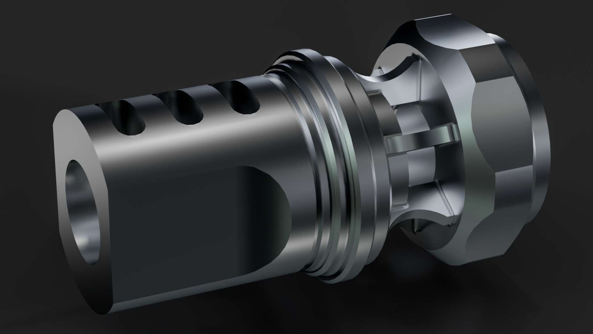
If you’re working with the bevel shader, you don’t need to throw your sub-d modeling skills in the bin. Traditional high poly modeling techniques can be used alongside the bevel shader workflow.
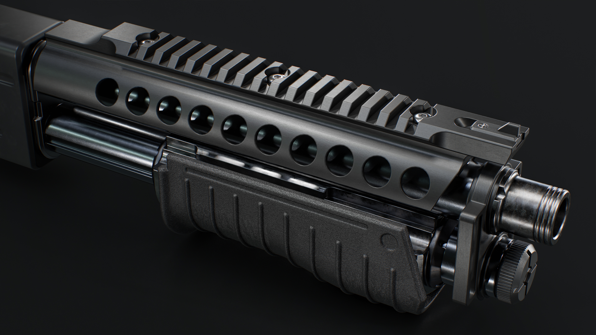
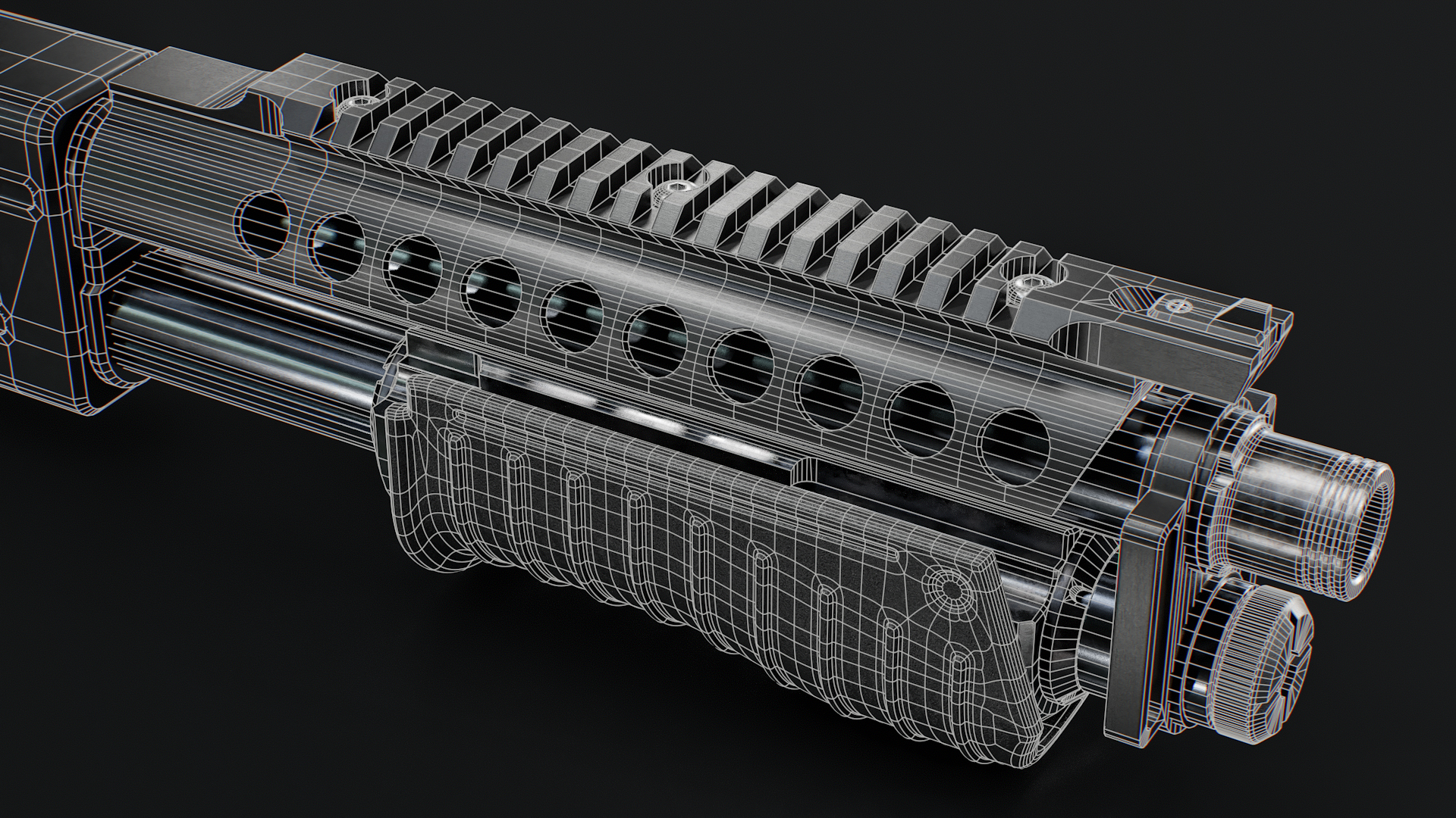
The image above uses relatively simple meshes and boolean modeling techniques with the bevel shader applied to round the edges for the majority of the parts. Sub-d is used for the pump, taking advantage of the ability to make smooth curves with ease. Mixing these techniques provides a great deal of flexibility, providing precise control over curves and edges where you need it and significantly speeding up the process when material-based bevels can be used.
Part Welding
You can create parts that appear to be welded or molded by intersecting different objects. This is a great trick that can save tons of time and make changes in design easier to manage. Since we don’t need to boolean or physically combine the meshes, the freedom to adjust the individual elements that make up a complex design is maintained.
If you don’t want nearby parts to appear welded, use separate mesh objects and enable the Bevel Same Surface Only setting in the corresponding material. This setting allows you to mix and match behaviors for complex assets. For example, it should be enabled for animated parts or separate pieces that are flush with another surface.
CAD
The bevel shader opens up new possibilities for where and how you create your 3D models. Cutting-edge asset creation workflows are becoming more reliant on CAD software, like Plasticity, to create detailed, complex assets. CAD workflows combine a level of accuracy and boolean flexibility that is hard to replicate in traditional polygon modeling software.

Art by Vitaliy Yablonskiy
Traditionally, polygon modeling software was preferred for hard-surface subdivision modeling as clean poly flow was essential for adding edge loops required to maintain forms. The bevel shading workflow adapts better to the topology generated by CAD software, making these applications a much more friendly, viable choice in a modern production environment.
That’s a Wrap!
While this article focuses primarily on hard-surface asset creation pipelines for games and real-time applications, the workflow applications are much broader. Character artists can use bevel shading for accessories and armor, while environment artists can easily knock out props and background objects. Bevel shading also has applications in film and can be used for look development and final quality renders for product and industrial design.

Alex Khaliman
Tech/Art Director @ Keal
“The Bevel Shader has revolutionized my workflow—delivering high-quality bakes without the need for high-poly models, cutting down days of work to mere hours, and optimizing file sizes.”

Thanks for reading! Start a free, 30-day trial for Toolbag today to speed up your hard surface workflow. For more Toolbag tutorials and quick guides, check out our Resources.